
A specialized type of schematic called a Ladder Diagram is generally used to show the sequence of operation of industrial control systems. They are valuable in both the engineering and troubleshooting of equipment. Often referred to as Ladder Logic Diagrams, they are also used in the programming of Programmable Logic Controllers (PLCs).
The diagram starts with a vertical ground or negative supply rails on the right and vertical positive rail or rails on the left. Horizontal rungs contain the circuit component connections. A rung contains controlling elements (switches, relay contact, etc.) on the left and controlled elements (Relays, motors, solenoids, etc.) on the right. Here is a quick example.
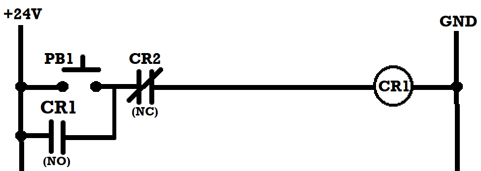
Following is a more complete example with an explanation of how it works:
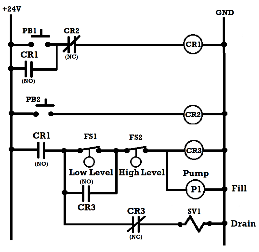
The diagram is a Ladder Diagram
CR=Control Relay PB=Push Button SV=Solenoid Valve
(NO)=Normally Open (NC)=Normally Closed
Note: The normal condition is the condition with no utilities applied
PB1 is a momentary push button ON switch to energize control relay CR1 which closes both sets of the CR 1 NO contacts. Power is then applied to the pump and CR3. The NC contacts open disconnecting power from SV1 blocking the drain. The NO contacts of CR3 close bypassing FS1 allowing the level until it reaches the high level. FS2 then opens turning the pump and CR3 off. The NC contacts of CR3 close applying power to SV1 opening the drain. As the level drops FS2 closes. When the low level is reached FS1 also closes starting the process over. As the level cycles over and over, PB2 can be used as an off switch.